STM-1 (Optical / Electrical) Add-Drop Multiplexer (with upto 16 E1 & 4 Ethernet) SDH Equipment
Description
Valiant offers STM-1 (Optical / Electrical), E1 and Ethernet Multi-Service SDH Transmission Unit is a modular platform unit with two 155.52Mbps optical / electrical interfaces, which may be used in a point-to-point, chain or ring application to provide an ultra-compact, cost effective and flexible multi-service platform.
Interface card options include the 8xE1 interface card (120 Ohms [RJ-45] and 75 Ohms [BNC]), 4x100BaseT Ethernet interface card (1 VCG, 4 Ports 1 Channel) and 4x100BaseT Ethernet interface card (4 VCG, 4 Ports 4 Channels) options along with Engineering Order Wire is available. The user removable / replaceable STM-1 Optical / Electrical interface option makes it easy to meet various and changing user requirements. Orion's STM-1, E1 and Ethernet over SDH Transmission Equipment provides full capability to cross-connect at E1 level between all tributaries

The equipment can be used as Terminal Multiplexer (TM) or an Add-Drop-Multiplexer (ADM) to build a point-to-point, ring and chain (add-drop) transmission network.
Related Links
Features and Highlights
- 1U height, 19-Inch standard rack-mountable chassis
- Service interfaces
- 2 x STM-1 optical interfaces, MSA compliant SFP (pluggable) optical module (LC connector) based design, which supports onsite optical port replacement
- 2 x STM-1 electrical interfaces, SFP electrical module (Mini BNC connector) Optional
- Maximum 16 E1 interfaces compliant with ITU-T G.703 (8 E1 interfaces per card)
- 120 Ohms E1 and 75 Ohms E1 interfaces options available
- 4 x 10/100BaseT Ethernet (electric) interface
- 10/100BaseT (FE) Ethernet Interface Options:
- 4 Ports, 4 Channels (4 VCG), and
- 4 Port 1 Channel (1 VCG)
- 1x GigE (Gigabit) Ethernet interface Options
- Optical GigE (Gigabit) Ethernet interface,
- Electrical 1000BaseT (Gigabit) Ethernet Interface
- Provides complete diagnostics facilities to the user for monitoring optical ports and provide reading of optical transmit power, optical receive power, laser temperature, bias current in voltage alarms etc.
- Performance Monitoring and Alarms - Error counts for B1, B2, B3
- Performance Analysis - Error Seconds (ES), Several Error Seconds (SES), Unavailable seconds (UAS), Higher Order Virtual Container - Remote Error Indication (HOVC-REI), Higher Order Virtual Container - Pointer Justification Event (HOVC-PJE)
- Management and Maintenance interfaces
- 10/100BaseT Ethernet management interface
- RS232 serial management interface
- Remote (Telnet) management interface
- Windows XP based Graphical User Interface (GUI)
- Windows 7 based Graphical User Interface (GUI)
- SNMP V2 Monitoring
- Engineering Order Wire (EOW) interface (RJ-11)
- NMS (Network Management System) for monitoring multiple units from a single / central location
- Timing mode
- Synchronization with STM-1 line timing
- Synchronization with timing from any of the E1 interfaces (1-16 E1 tributary interfaces)
- External timing source option - 120 Ohms 2MBps (External Bits Clock)
- External timing source - 120 Ohms 2MHz (External TTL Clock) - Factory Configurable
- Internal Clock - ITU-T G.813 internal oscillator (Stratum 3)
- The timing source can be auto-switched according to default or operator programmed settings
- Ethernet Standards Conformity
- Generic Framing Procedure GFP-F compliant with ITU-T G.7041
- VCAT compliant with ITU-T G.707 and LCAS compliant with ITU-T G.7042
- Ethernet flow control on WAN port and LAN port
- Large buffer size upto 410,000 bytes
- Maximum Frame length (MTU size):1536 bytes with 4 port 1 channel (1 VCG) Ethernet Card
- Maximum Frame length (MTU size):2036 bytes with 4 port 4 channel (4 VCG) Ethernet Card
- Auto MID/MID-X for Ethernet Interfaces
- Support 802.1Q based VLAN tagging (4 ports 1 channel (1 VCG) Ethernet Card only)
- Support Port based VLAN tagging (4 ports 1 channel (1 VCG) Ethernet Card only)
- Performance Analysis
- All Received Packets
- All Transmitted Packets
- Received Dropped Packets
- Supports 1+1 Line Protection and Automatic Protection Switching (APS) with less than 50ms recovery
- Supports point-to-point, ring and chain topology (4 VCG card only)
- Local management and network-based management via a unified platform
- Supports Remote Power Down Detection and Auto Laser Shutdown
- Supports STM-1 and E1 loop-back for troubleshooting
- 850nm multi-Mode, 1310nm Single Mode and 1550nm Single Mode optical interface options offered
- Ethernet mapping adopts GFP/VC-12 virtual concatenated technology; according with MSTP criterion
- Provides Ethernet over SDH mapping through standard GFP and VC-12 virtual concatenation (VCAT)
- Ethernet bandwidth can be adjusted by the user between 2MBps ~126 Mbps (VC-12 mapping)
- Supports MAC Address list filtration, learning and updating function
- Easy to operate
- Redundant power supply card options AC+DC, DC+DC and AC+AC
- 110V AC - 240V AC (50/60 Hz) power options available
- -48V DC power option available
- -24V DC power option available
- Power consumption less than 17W.
Alarm and Indicator Monitoring
- Power Indicator
- Current Status (integrity and activity) Indicator
- Urgent Alarm Indicator
- Minor Alarm Indicator
- Optical Signal Loss Alarm Indicator
- Remote Device Power-down Indicator
- Ethernet Card Status Indicator
- General Alarm Indicator for Ethernet Card (including Link-down of Ethernet Port)
- Auto Laser Shutdown (ALS) Indicator
- Engineering Order-Wire (EOW) Indicator
- Ethernet Link Indicator
- Ethernet Speed Indicator
- E1 Card Status Indicator
- Dry contact via 9-pin, D-type male connector
- Buzzer Alarm
- SNMP Diagnostic and Monitoring
Application Diagram
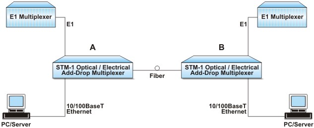
Application # 1: Point to point Network Application Diagram

Application # 2: Chain Network Application Diagram

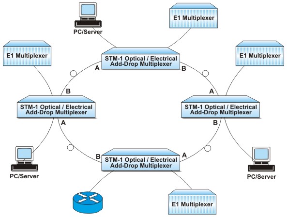
Application # 3: Ring Network Application Diagram

